01 · Easy start
First sound, no development tools.
If your Core arrived with a prepared SoundGraph microSD card, this is the shortest safe path. A prepared card has a start.bin file at its root.
- Turn the listening level down.Lower the headphone, mixer, interface, amplifier, or powered-speaker gain before connecting anything.
- Insert the microSD card while power is off.Use a FAT32 card. The gold contacts face the PCB; align it carefully and never force the slot.
- Connect one audio output.Use the 6.35 mm stereo line output for a mixer or interface, or the 3.5 mm headphone output for headphones.
- Connect a controller if the patch expects one.Use DIN MIDI IN, or plug a class-compliant USB MIDI controller into the USB-A host port.
- Apply power.For a first test, use a known-good micro-USB data cable from a computer or USB supply. For standalone use, a correct 7.5–15 V center-positive DC adapter also works.
- Wait for the boot patch, then raise the level slowly.The stock firmware loads
/start.binat power-on. MIDI Program Change selects entries from a baked SoundGraph bank.
02 · Board connections
What every port does.
The three audio jacks are easy to misread: line input and line output are each stereo on one 6.35 mm TRS jack; the smaller jack is a separate stereo headphone output.
| Connection | Connector and cable | Use |
|---|---|---|
| Power / programmer | Micro-USB device portMicro-USB data cable | Powers the board, programs it, carries the Axoloti vendor USB connection, and exposes class-compliant USB MIDI. |
| USB host | USB Type-A socketThe cable supplied with the MIDI controller | Connects a class-compliant USB MIDI keyboard, pad controller, or control surface directly to the Core. |
| DC power | 5.5 × 2.1 mm barrel jackRegulated 7.5–15 V DC, center-positive adapter | Runs the board without a computer. Never use AC, center-negative power, or more than 15 V. |
| Audio input | 6.35 mm (¼-inch) TRS stereo jackStereo TRS or TRS-to-dual-TS breakout | Two channels of line-level audio on one jack. It is stereo TRS, not a balanced mono input. |
| Audio output | 6.35 mm (¼-inch) TRS stereo jackStereo TRS or TRS-to-dual-TS breakout | Two channels of line-level audio on one jack. Begin with the downstream gain turned down. |
| Headphones | 3.5 mm (⅛-inch) TRS stereo jackOrdinary stereo headphones or a 3.5 mm stereo cable | Headphone-level stereo monitoring. Start quietly when loading an unfamiliar patch. |
| MIDI input | 5-pin DINStandard 5-pin DIN MIDI cable | Receives note, controller, clock, and program-change messages from conventional MIDI gear. |
| MIDI output | 5-pin DINStandard 5-pin DIN MIDI cable | Sends conventional DIN MIDI from a patch. |
| Storage | microSD slotmicroSD card; a card reader is useful for preparing it | Stores a boot patch, SoundGraph patch banks, samples, and other patch data. |
| Expansion I/O | Labeled 2.54 mm pads / optional headers0.1-inch headers, jumpers, or a purpose-built shield | Breaks out GPIO, ADC, two DAC outputs, SPI, I²C, UART, ground, 3.3 V, analog 3.3 V, and 5 V rails. |
03 · Power
USB is easiest. DC is specific.
- Input
- 7.5–15 V DC
- Plug
- 5.5 mm outer / 2.1 mm inner
- Polarity
- Center positive
- Alternative
- 5 V through micro-USB
Use a regulated DC adapter. The board schematic connects the barrel center contact to the protected VIN path and the sleeve to ground. Choose an adapter with enough current for the Core and anything drawing power from its USB host port.
- Never use an AC-output adapter.
- Never use a center-negative supply.
- Never exceed 15 V at the barrel jack.
- Do not inject power into the expansion rails unless you understand the board’s power path.
- When a USB controller causes resets, test without it or use a controller with its own power.
04 · microSD
Small, ordinary, FAT32.
The stock Axoloti 1.0.12-2 firmware uses a FatFs configuration without exFAT. A 64 GB-or-larger SDXC card normally arrives as exFAT and will not work until reformatted; a native FAT32 SDHC card avoids that friction. Speed class is not the bottleneck for this workflow.
For a standalone SoundGraph bank, the card contains:
/start.bin             boots at power-on
/index.axb             lists bank entries
/<patch-name>/patch.bin
/<patch-name>/b0.raw  optional sample or speech data
Program Change 0 selects the first bank entry. Out-of-range program numbers fall back to /start.bin. Power the board off before inserting or removing the card.
05 · Programming
What “program the board” means.
- 1GraphSave the SoundGraph patch as JSON.
- 2ResolveSoundGraph expands modules, checks the graph, and fixes execution order.
- 3Generate
sgaxoturns supported nodes into Axoloti C++. - 4CompileThe ARM toolchain links a patch binary against stock firmware symbols.
- 5InstallUpload over micro-USB for development, or copy a baked bank to microSD.
- 6RunThe firmware starts the binary; the card can boot it without a computer.
Prepare the developer tools
From a SoundGraph source checkout, first build the graph validator. Then prepare the Axoloti SDK and Python environment. The package-install line below is for macOS with Homebrew; use equivalent packages on Linux.
cmake -S . -B build -DCMAKE_BUILD_TYPE=Release
cmake --build build --target sg-validate

cd embedded/axoloti
brew install libusb arm-none-eabi-gcc arm-none-eabi-binutils
python3 -m venv .venv
.venv/bin/pip install -r requirements.txt
tools/fetch-sdk.sh
Compile one graph
.venv/bin/python sgaxo/codegen.py ../../examples/patches/first-synth.jsonThe compiled files land in embedded/axoloti/sgaxo/build/. This command proves the patch compiles; the current repository’s hardware-in-the-loop tools perform tethered USB upload and start.
Bake a standalone card
.venv/bin/python tools/bake-bank.py ./card \
  ../../examples/patches/first-synth.json \
  ../../examples/patches/plucked-string.json
Copy the contents of ./card to the root of a blank FAT32 microSD card. A card reader is fastest. Advanced users can add --board to write through a connected Core, but USB card writes are much slower.
06 · Legacy software
Two patchers, one important firmware choice.
Original
Axoloti Patcher
The original Java patcher and the best historical reference for .axp, .axs, .axo, and .axh files. Connect the Core by micro-USB, choose Board → Select Device, connect, open a patch, and enable Live.
Going Live generates compatible code, compiles it, uploads the binary, and starts it. Leave Live mode before changing the graph; only one patch can run on a board at a time.
Axoloti 1.0.12-2 releaseMaintained fork
Ksoloti Patcher
The standalone Ksoloti Patcher has legacy support for original Axoloti Core boards. It can work with only one board family at a time, so select Axoloti rather than Ksoloti when configuring it.
Firmware warning: SoundGraph’s current backend targets stock Axoloti 1.0.12-2. Do not accept a firmware replacement prompt unless you mean to switch this board to the Ksoloti workflow and are prepared to restore stock firmware later.
07 · Expansion pinout
The labeled edge pads.
Axoloti names expansion pins by STM32 port: PA0 means MCU port A, pin 0. The board exposes the groups below. Use the labels printed on the PCB and the official schematic for physical placement; this responsive table describes electrical function, not left-to-right pad position.
| Pins | Analog function | Common alternate function |
|---|---|---|
PA0–PA3 | ADC1 IN0–IN3 | General-purpose digital I/O |
PA4 | ADC1 IN4 | DAC OUT1 · SPI NSS · GPIO |
PA5 | ADC1 IN5 | DAC OUT2 · SPI SCK · GPIO |
PA6 | ADC1 IN6 | SPI MISO · GPIO |
PA7 | ADC1 IN7 | SPI MOSI · GPIO |
PB0–PB1 | ADC1 IN8–IN9 | General-purpose digital I/O |
PB6–PB7 | — | UART TX / RX · GPIO |
PB8–PB9 | — | I²C1 SCL / SDA · GPIO |
PC0–PC5 | ADC1 IN10–IN15 | General-purpose digital I/O |
VDD | — | 3.3 V digital rail |
VDDA | — | 3.3 V analog rail |
+5V / GND | — | 5 V supply rail and return |
The board also exposes SWD test points and separate MIDI test points; those are service and hardware-development connections, not ordinary user I/O. See sheet 6 of the schematic for the expansion pads and sheet 7 for MIDI.
08 · MIDI controllers
Remap by moving the control you mean.
Bind a hardware CC to a face knob
- Connect the controller before opening SoundGraph. The desktop editor opens the operating system’s MIDI inputs automatically.
- Open the patch’s Rack view. The target knob must already be exposed on the patch’s Face.
- Hold Ctrl and click the SoundGraph knob you want to control.
- When the status message says MIDI Learn is armed, move the desired hardware knob, fader, or pedal.
- The next MIDI Control Change message replaces that control’s prior binding. Save the patch to keep the mapping.
Press Escape before moving a controller to cancel Learn. Incoming CC values use the SoundGraph control’s own range and scaling, so a logarithmic frequency control still feels logarithmic.
Use a MIDI CC as a graph signal
Add a MIDI CC node when the controller should become a cableable modulation source instead of directly turning a face knob. Press Learn on that node, then move the desired hardware control. The node stores:
- CC
- The controller number. CC 1 is normally the modulation wheel; set this field to 128 manually when you want pitch bend.
- Low / high
- The output range produced by MIDI values 0–127.
- Resting
- The value used before that controller has sent anything.
- Glide
- Smoothing that removes abrupt steps from knob movement.
09 · Design files
The attached mechanical references.
These files help with enclosure fit, cutting, and CAD. They do not define power requirements or signal pinouts; use the schematic for electrical work.

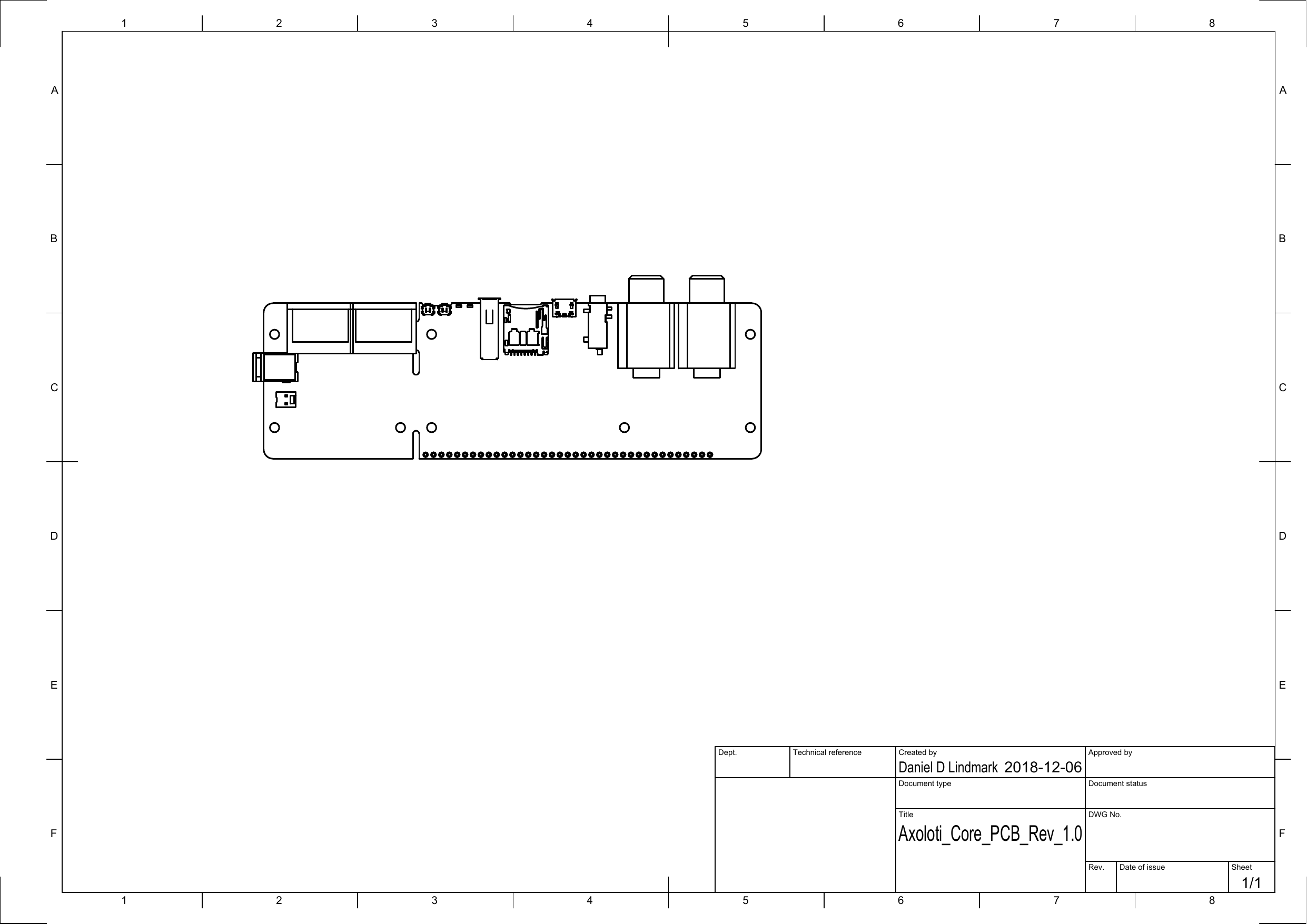
Top-view mechanical reference for the Axoloti Core PCB Rev 1.0.
Download Six-up enclosure layout SVG · 790 × 384 mm sheet · 6 KBVector cutting layout for six Believotron Core enclosures with a short 3 mm overhang.
Download PCB model STEP AP214 · Rev 1.0 · 4.7 MB3D mechanical model for enclosure and assembly work.
10 · Troubleshooting
Start with the boring causes.
The computer does not see the Core.
Replace the micro-USB cable with one known to carry data, not just charging power. Disconnect the USB-host controller, reconnect the Core directly to the computer, and confirm the board LEDs come on. In legacy Axoloti, use Board → Select Device before Connect.
The board resets when I play the USB controller.
The controller may draw more power than the board or upstream USB port can comfortably provide. Test with the controller disconnected, use DC power with the correct specification, or power the controller separately if its design permits.
The microSD card is ignored.
Confirm it is 32 GB or smaller and formatted FAT32, then confirm start.bin is at the card root rather than inside another folder. Power down, reseat the card, and try a second name-brand card.
The patch compiles on desktop but not for Axoloti.
The Axoloti target intentionally supports a tested subset of SoundGraph nodes and has a small patch code window. Read the compiler’s named refusal; remove or replace the unsupported node instead of assuming the graph was uploaded.
The patch runs but produces no sound.
Check that you used stereo line output, not input; confirm the patch reaches a Stereo Output node; send a MIDI note if the patch expects one; and increase downstream gain slowly. For a bank, send Program Change 0 or reboot to load start.bin.
Reference desk
Primary sources.
- SoundGraph Axoloti target and tested workflow
- Original Axoloti user guide
- Ksoloti installation guide
- Axoloti Core v1.0 schematic
- Axoloti / Ksoloti hardware comparison
Scope: original Axoloti Core revisions 1.0 and 1.2. The downloadable mechanical files on this page identify PCB Rev 1.0; compare any enclosure work against the physical board in front of you.